Specific resistance of a wire (heater) calculated under the formula:
at substitution of value of temperature in oC – Rs = R0 · [1+a · (T-20)], [1]
at substitution of value of temperature in K – Rs = R0 · [1+a · (T-293)], [1]
where
R0 – specific electrical resistance at temperature 20°C, Ohm · sm [104 · Ohm · sm = Ohm · mm 2 / m];
a – a resistance temperature coefficient, 1/°C [1/K];
T – wire temperature, °C [K].
Electrical resistance of a site of a wire pays off under the formula:
R = Rs · L / S, [2]
where
L – wire length, sm [m];
S – a wire sectional area, sm2 [mm2].
Electric heater power [W] is calculated as follows:
P = U2 / R, [3]
where
U – voltage, V;
Quantity heat imparted to the wire q = P [ J/s ]
The circuit design of nomographs is presented in drawing 1.
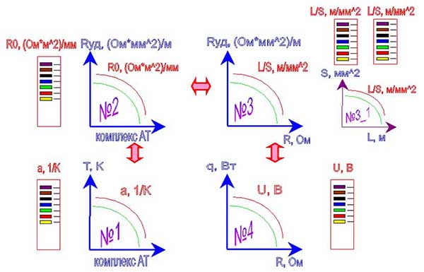
Drawing 1. The circuit design of system of nomographs
After applet start an auxiliary window will have the following appearance (drawing 2).
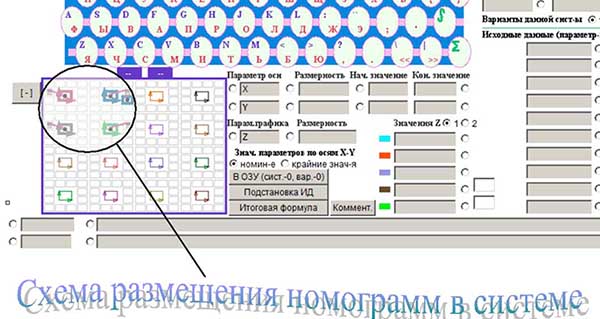
Drawing 2. An additional window of an applet on build-up of system of nomographs
In an auxiliary window the circuit design of disposing of nomographs is already shown, but she demands recurring feeding into, therefore on each small square which is marking out a nomograph "is clicked" by the right key of the mouse and the left key "clicked"on that place where there should be a colour flag indicator (a place of disposing of meaning of parametre Z of a nomograph). It is possible choose any other location of variable parametre Z. After recurring appointment of the circuit design of nomographs "is clicked" by the left key of the mouse on sign "[-]", had in left overhead to the angle of the circuit design of nomographs. It will change the aspect on "[+]". It means, that the circuit design of nomographs is fixed.
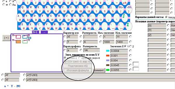
Drawing 3. An additional window of an applet on build-up of system of nomographs with the tuned circuit design of nomographs
After attaching of the circuit design of nomographs, "is in succession clicked" on everyone sign, marking out a nomograph, and it is pushed three buttons "In the working memory" ("В ОЗУ"), "Substitution ID" ("Подстановка ИД"), "the Total formula" ("Итоговая формула") for entering of all parametres of a nomograph into an on-line storage and design formula formation.
We transfer to the basic window and we induct meanings of steps on axes "X" and "Y". We push the button "to Build on ID" ("Построить по ИД").

Drawing 4. The basic window of an applet for build-up of system of nomographs.
More detailed instruction on operation with an applet.
graphic-analytical systems
Copyright © 2005-2022 All rights reserved